
77
Specifications subject to change. See bluesea.com for current information.
C O N N E C T O R S A N D I N S U L AT O R S
See page 76 for compatible
enclosure 2718
Specifications
Continuous Rating
545A AC/600A DC
Voltage Max. Operating 300V AC/48V DC
Mounting Holes
2104—Accepts 1 ∕4" Screws
2107—Accepts #10 (M5) Screws
Bus Material
Tin-Plated Copper C11000
Regulatory
E
Certified
PN
Terminal
Studs
Terminal
Screws
[A] Length
in (mm)
[B] Mounting
Centers in (mm)
2104
4 × 3 ∕8" -16
4 x #8-32 7.0 (177.8)
6.25 (158.74)
2107
8 × 3 ∕8" -16
4 x #8-32 11.375 (288.93) 10.375 (263.53)
2708 Cover For 2104
PowerBar -
600A Common BusBars
Highest amperage BusBar with 3/8" terminal studs
2104
2107
2708
[A]
[B]
1.25" (31.75mm)
Typical
2.00"
50.80mm
1.32"
33.53mm
Overall Height
Approx. 2.00" (50.80mm)
1.875"
47.63mm
1.63"
41.30mm
0.848"
21.54mm
2.75"
69.85mm
1.5"
38.10mm
1.25"
31.75mm
Specifications
Continuous Rating
up to 200 Amps
Voltage Max. Operating 48V DC
Mounting Holes
Accepts #10 (M5) Screws
Bus Material
Tin-Plated Copper C11000
Regulatory
E
Certified
2019
PowerBar Common BusBars
Provides compact high-amp busing with 3∕ 8" terminal studs
PN
Terminal Studs
Insulators
2019
2 × 3 ∕8" -16
Included
2020
2 × 3 ∕8" -16
-
See page 76 for compatible enclosure PN 2719
Specifications
Bus Material
Nickel-Plated Brass
Continuous Amperage Equivalent to matching block
2404
2504
2608
•
Each screw pair is one isolated circuit
•
Terminal Block Jumpers allow creation of common circuits
•
Closed back design completely insulates power from the mounting surface
Specifications
Continuous Rating
See table below
Voltage Max. Operating
See table below
Bus Material
Tin-Plated Brass
Mounting Holes
See drawings below
Regulatory
E
Certified
9217
PN
Description
Retail Pack
9218 For use with 20A Terminal Blocks
5
9217 For use with 30A Terminal Blocks
5
9216 For use with 65A Terminal Blocks
5
PN Circuits
AC/DC AC/DC Terminal
Screw
Drawing
Number
[A] Length
in (mm)
[B] Mounting
Centers in (mm)
2402 2
20
300
#6
1
1.41 (35.81)
1.13 (28.70)
2404 4
20
300
#6
1
2.16 (54.86)
1.88 (47.75)
2406 6
20
300
#6
1
2.91 (73.91)
2.63 (66.80)
2408 8
20
300
#6
1
3.66 (92.96)
3.38 (85.85)
2410 10
20
300
#6
1
4.41 (112.01)
4.13 (104.90)
2502 2
30
600
#8
2
2.10 (53.34)
1.69 (42.93)
2504 4
30
600
#8
2
3.22 (87.79)
2.81 (71.37)
2506 6
30
600
#8
2
4.34 (110.24)
3.93 (99.82)
2508 8
30
600
#8
2
5.46 (138.68)
5.05 (128.27)
2510 10
30
600
#8
2
6.58 (167.13)
6.17 (156.72)
2512 12
30
600
#8
2
7.70 (195.58)
7.29 (185.17)
2602 2
65
600
#10
3
2.50 (63.49)
2.06 (52.32)
2604 4
65
600
#10
3
3.88 (98.55)
3.44 (87.38)
2606 6
65
600
#10
3
5.26 (133.61)
4.82 (122.43)
2608 8
65
600
#10
3
6.64 (168.67)
6.20 (157.48)
2610 10
65
600
#10
3
8.02 (203.73)
7.58 (192.53)
Mounting
hole for
#6 Screw
0.31"
7.87mm
0.375"
9.53mm
0.88"
22.35mm
Overall Height
Approx. 0.47" (11.9mm)
[B]
[A]
1.31"
33.27mm
Mounting
hole for
#10 Screw
0.50"
12.70mm
[B]
[A]
Overall Height
Approx. 0.71" (18.0mm)
0.56"
14.22mm
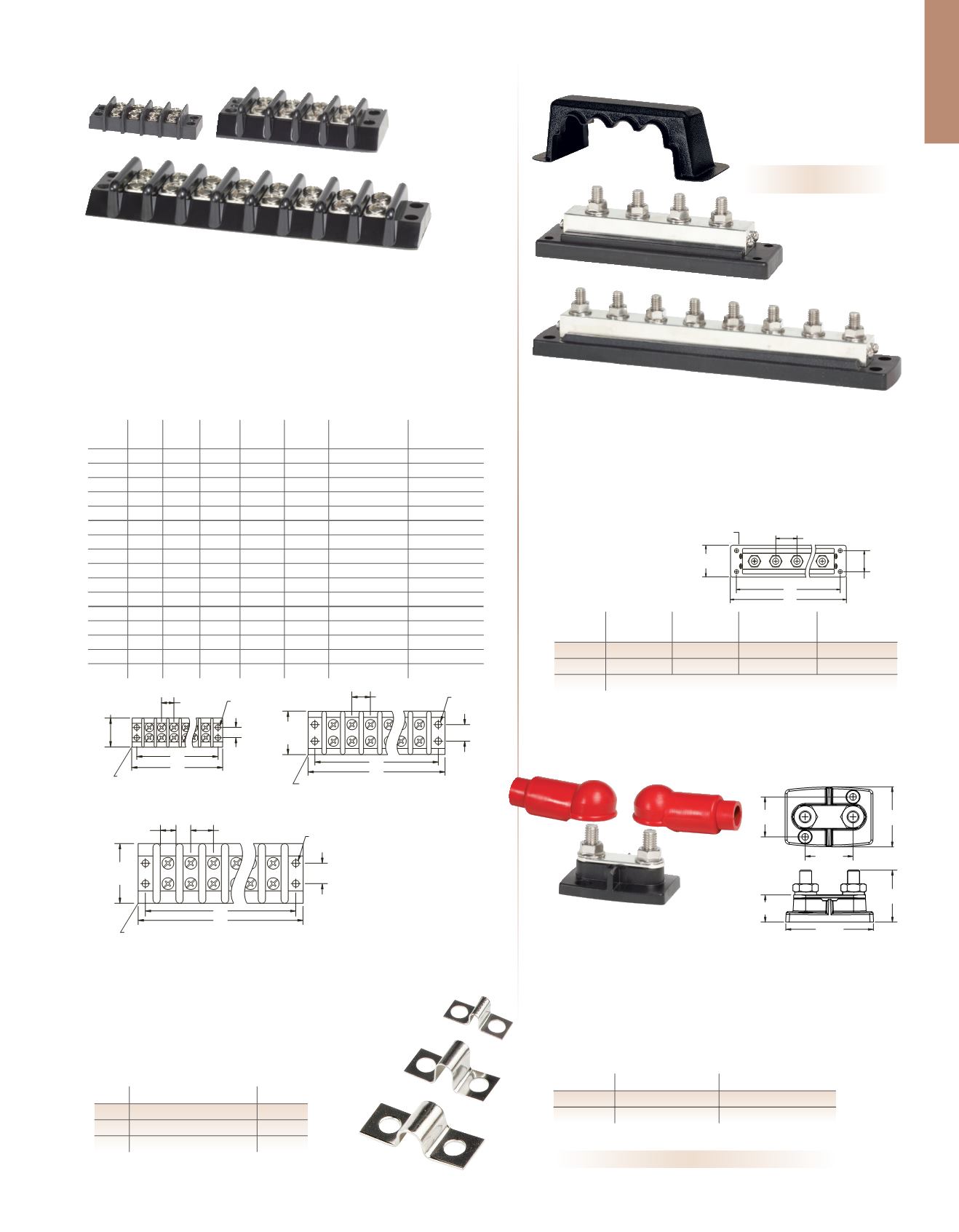
Drawing 2 (2502–2512)
Mounting
hole for
#10 Screw
0.62"
15.75mm
[B]
[A]
Overall Height
Approx. 0.75" (19.1mm)
1.81"
45.97mm
0.69"
17.53mm
0.49"
12.45mm
Drawing 3 (2602–2610)
Drawing 1 (2402–2410)
Terminal Blocks
Fully insulated independent terminal blocks to isolate circuits
Terminal Block Jumpers
Combines independent circuits on a terminal block (above)
and ST-Blade Fuse Blocks PNs 5035 and 5037 (p. 44)
9216
9218


