
4
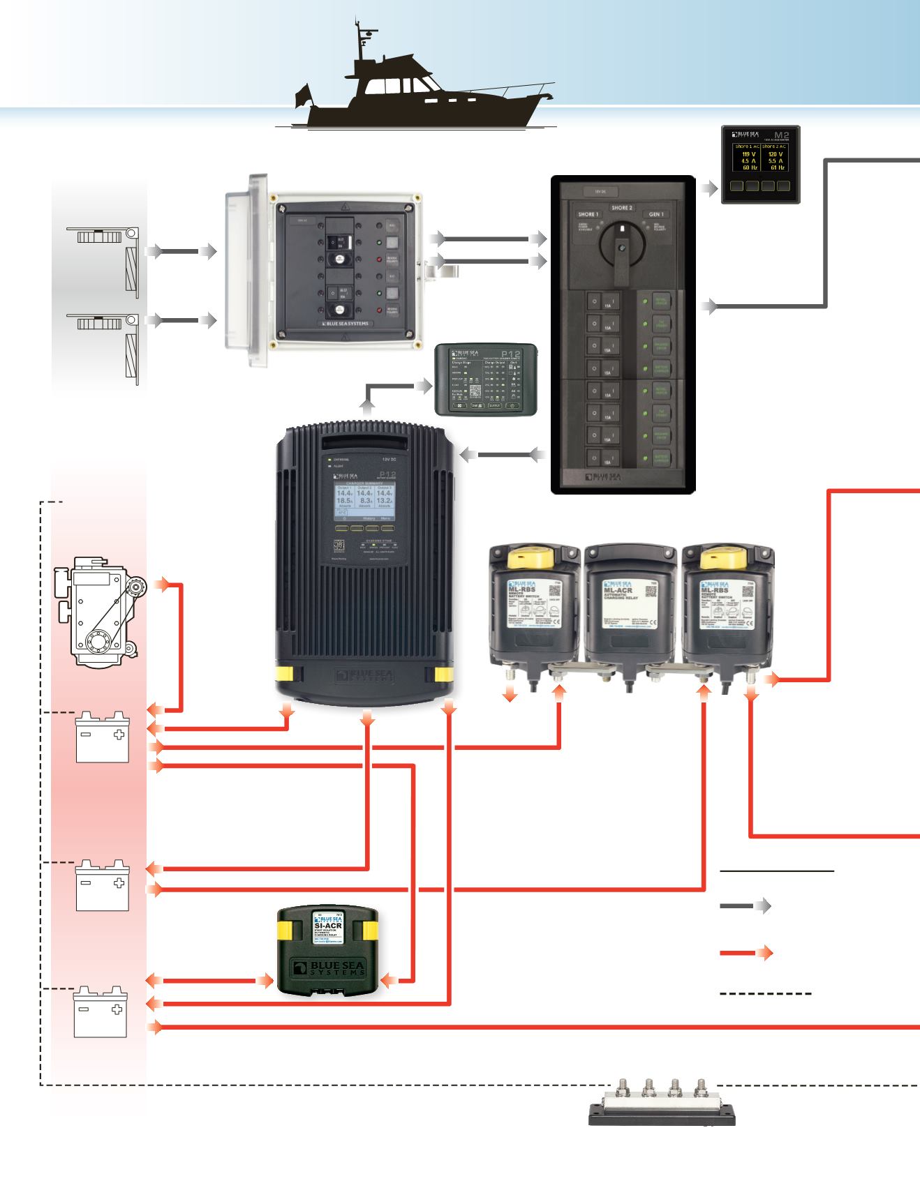
The diagram above is intended for reference only. Consult an ABYC certified marine electrical professional for system design and circuit protection.
System Diagram
Shore
Power 1
Engine
Engine
House
Auxilliary
AC Current
Surface
Mount
System
(
p. 65)
Custom
360 AC
Panel
(
p. 106)
P12
Battery
Charger
(
p. 10)
SI-ACR
Automatic
Charging
Relay
(
p. 30)
ML-RBS
(
p. 26)
ML-ACR
(
p. 32)
ML-RBS
(
p. 26)
DC Current
Alternator
Engine Start
M2 AC
Multimeter
(
p. 117)
Shore
Power 2
AC
SOURCES
DC
SOURCES
DC Ground
PowerBar 600
(
p. 77)
LEGEND
P12 LED Remote
(
p. 11)
3 Battery Bank, 1 Engine
Yacht System


