
C I R C U I T P R O T E C T I O N
69
Specifications subject to change. See bluesea.com for current information.
8268
8266
8267
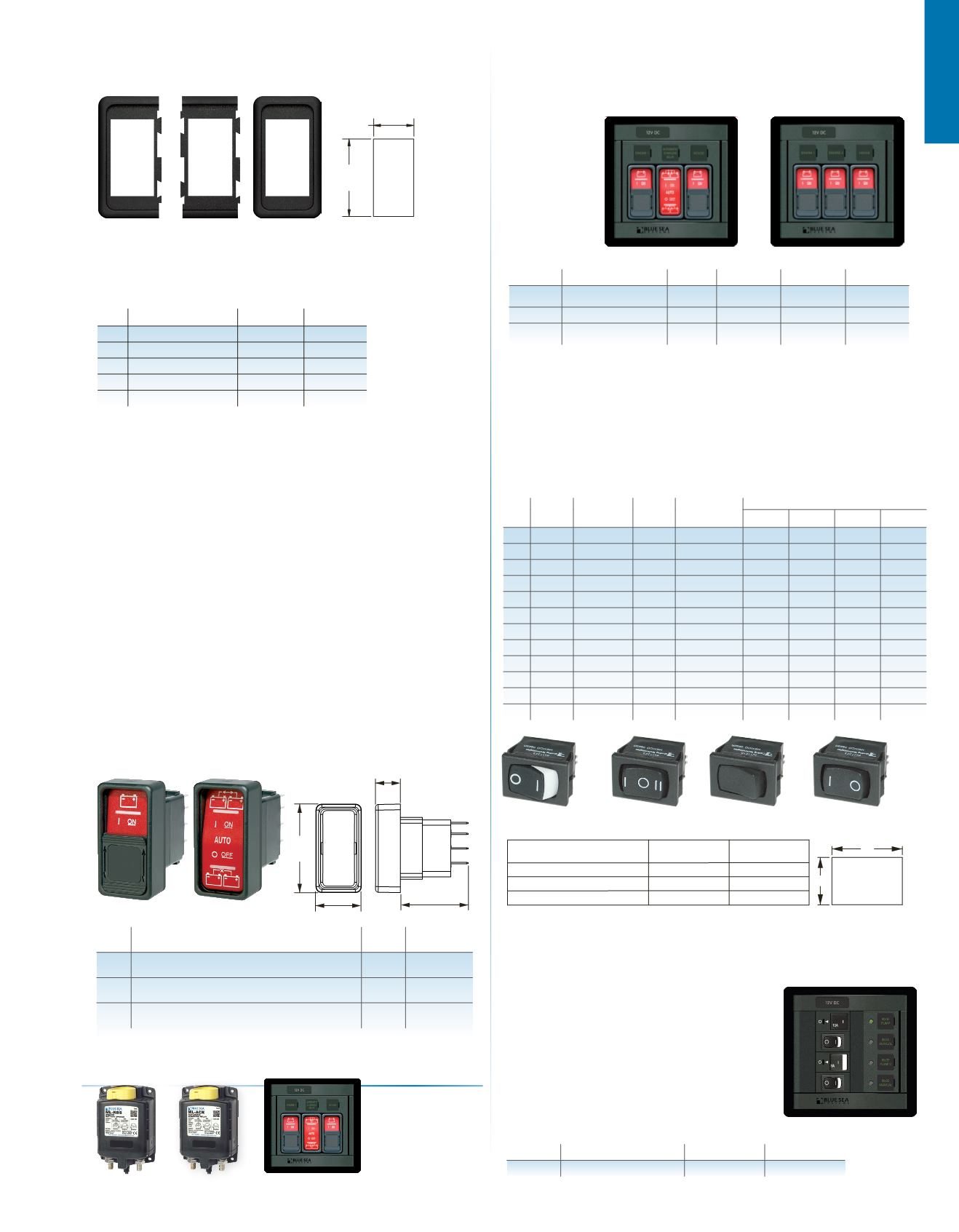
Contura Switch Mounting Panels
Modular design permits assembly in groups of varying sizes
0.984"
25.00mm
FOR ADDITIONAL
UNITS, ADD
1.03"/26.2mm
PER UNIT
1.900"
48.20mm
TEST CUT
HOLE IN
ACTUAL
MATERIAL
PN
Description
Width in (mm)
Height in (mm)
8267
End Mounting Panel
1.19 (30.23)
2.30 (58.42)
8266
Center Mounting Panel
1.03 (26.16)
2.30 (58.42)
8268 1 Position Mounting Panel
1.34 (34.04)
2.30 (58.42)
8259 3 Position Mounting Panel
3.40 (86.36)
2.30 (58.42)
8260 6 Position Mounting Panel
6.49 (164.85)
2.30 (58.42)
Cutout Dimensions
Features
•
Vibration, shock, thermoshock, moisture and salt spray resistant
•
Lockout slide reduces the risk of accidental switching 2145 and 2155
Specifications
Amperage Max. Operating
20A @ 12V DC, 15A @ 24V DC
Amperage Operating Current
18mA
Temperature Range
-40°C
–
85°C
Pole/Throw
SPDT
Lighting
LED rated 100,000 hours half-life
Seals
Internal and external gasket
panel seal
Mounting Hole
1.45" x 0.83"
(36.83 mm x 21.08 mm)
Regulatory
Meets UL 1500 and ISO 8846 external ignition protection requirements
IP67—protected against immersion up to 1 meter for 30 minutes
(see inside back cover)
2145, 2155
2146
Remote Control Contura Switches
Provide remote switching of ML-Series, and SafetyHub
250 Fuse Block
PN For Use With:
Pole
Throw
Action
( )=momentary
2145
ML-Series Solenoids, 7701 and 7703 (p. 23)
ML-Series Remote Battery Switches, 7700 and 7702 (p. 26)
SPDT (ON)-OFF-(ON)
2146
ML-Series Automatic Charging Relays,
7620, 7622, 7621, and 7623 (p. 32)
SPDT ON-OFF-ON
2155 ML-Series Remote Battery Switches, 7713 and 7717 (p. 26)
SPDT ON-ON
1.01"
5.7mm
1.965"
49.9mm
1.51"
38.35mm
.55"
14mm
•
Mounting panels available in 1, 3, and 6 fixed position models
•
Designed for mounting in 6 different panel thicknesses:
0.06 in (1.57 mm) 0.09 in (2.36 mm) 0.13 in (3.17 mm)
0.19 in (4.75 mm) 0.25 in (6.35 mm) 0.38 in (9.52 mm)
360 Panel Rocker Switches
Provides switching options for specific pole and throw configurations
Specifications
Amperage Max. Operating
See table below
Single Pole Terminal Type
Quick Connect Tab
Single Pole Terminal Size
0.187 in (4.80 mm) Quick Connect Tabs
Double Pole Terminal Type
6.00 in (152.00 mm) Wire Leads
PN Pole-Throw
Terminal
Type
Illustration
Below
Action
( ) = Momentary
Amperage Maximum Operating
12V DC 24V DC 125V AC 250V AC
7480 SPST Quick Connect
1 OFF–ON
10 Amps 10 Amps 10 Amps 10 Amps
7481 SPST Quick Connect
1 OFF–(ON)
10 Amps 10 Amps 12 Amps 6 Amps
7482 SPDT Quick Connect
2 ON–OFF–ON 10 Amps 8 Amps
8 Amps
8 Amps
7483 SPDT Quick Connect
2 (ON)–OFF–ON 10 Amps 8 Amps
8 Amps
8 Amps
7484 SPDT Quick Connect
2 (ON)–OFF–(ON) 10 Amps 8 Amps
8 Amps
8 Amps
7485 SPDT Quick Connect
4 (ON)–OFF–(ON) 10 Amps 8 Amps
8 Amps
8 Amps
7490 DPST
Wire Leads
1 OFF–ON
5 Amps
5 Amps
8 Amps
4 Amps
7491 DPDT
Wire Leads
3 ON–ON
5 Amps
5 Amps
8 Amps
4 Amps
7492 DPDT
Wire Leads
2 ON–OFF–ON
5 Amps
5 Amps
8 Amps
4 Amps
7493 DPDT
Wire Leads
3 ON–(ON)
5 Amps
5 Amps
8 Amps
4 Amps
7494 DPDT
Wire Leads
2 (ON)–OFF–ON 5 Amps
5 Amps
8 Amps
4 Amps
7495 DPDT
Wire Leads
2 (ON)–OFF–(ON)
5 Amps
5 Amps
8 Amps
4 Amps
2
3
4
Dual Bilge Pump 360 Panel
Controls two bilge pumps with restricted-off circuit breakers
and manual override switches
PN
Description
Width in (mm)
Height in (mm)
1522
Dual Bilge Pump Control Panel
4.88 (123.83)
4.75 (120.65)
PANELTHICKNESS
.078" (1.98mm)-.125" (3.17mm)
.050" (1.27mm)-.078" (1.98mm)
B
A
TEST CUT
HOLE IN
ACTUAL
MATERIAL
+.000 [.00] -.004 [.10]
.030" (.76mm)-.050" (1.27mm)
.756" (19.20mm)
.780" (19.81mm)
.764" (19.40mm)
Recommended Panel Opening
.508" (12.90mm)
.508" (12.90mm)
.508" (12.90mm)
A
B
1
Related Products
ML-Series ACR
p. 32
ML-Series RBS
p. 26
1148 Switches:
2145 (3)
1147 Switches:
2145 (2); 2146 (1)
Remote Control Switch 360 Panels
Use with ML-Series Remote Battery Switches
or Automatic Charging Relays
PN
Description
Max. Volts Width in (mm) Height in (mm) Depth in (mm)
1147 2 RBS and 1 ACR
switch panel
24V DC 4.88 (123.83) 4.75 (120.65) 2.00 (50.80)
1148 3 RBS switch panel
24V DC 4.88 (123.83) 4.75 (120.65) 2.00 (50.80)
1520 Blank switch panel
accepts 3 Switches
-
4.88 (123.83) 4.75 (120.65) 0.125 (3.175)
•
Backlit labels
•
Lockout slides
•
Square format
label set 4218
(p. 129)
Remote Control
Contura Panels p. 69
1522
•
Controls two bilge pumps
•
Restricted-OFF circuit breakers provide 24-hour
circuit protection to the bilge pump float switch.
•
On-indicating LED indicates power is available
at the bilge pump float switch.
•
Manual Override switch with On-indicating LED
provides visual indication pump is running;
also illuminates when pump is running as
a result of float switch operation.


