
133
A P P E N D I X
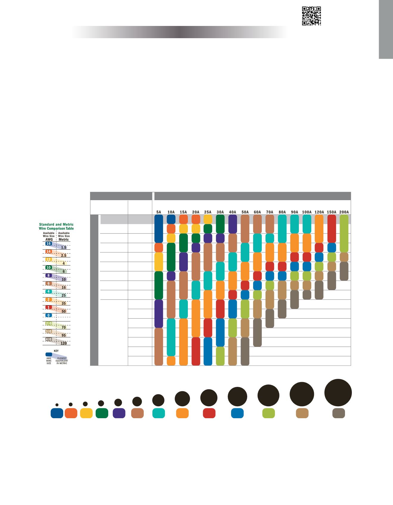
STEP 1 Choose the Correct Wire
Locate the
CURRENT FLOW IN AMPS
of your circuit along the top of the
WIRE SELECTION CHART
.
Select the
CIRCUIT TYPE
.
• Non-critical circuits with 10% allowable voltage drop include:
general lighting, windlasses, bait pumps, general appliances
• Critical circuits with 3% allowable voltage drop include:
panel main feeders, bilge blowers, electronics, navigation lights
Find the
CIRCUIT LENGTH
along the left side of the
WIRE SELECTION CHART
.
• The circuit length
is the length of the negative wire added to the length of the positive wire.
• Calculations are based on 105°C wire.
For wire rated at 90°C or lower, or for wire that passes through an engine room,
the first row of the chart, in gray, does not apply.
Intersect the
CURRENT FLOW IN AMPS
with
CIRCUIT LENGTH
to identify the correct wire size.
Example: A windlass rated 80A is 25 ft. from the battery. The circuit length is the total length of the positive
and negative wire added together, which in this example is 50 ft. The circuit type is ‘non-critical’, and the correct
wire size is 4 AWG.
A
B
C
D
With the Correct Size Wire and Fuse
Protect Your Boat
Scan to download
the app or go to
www.circuitwizard.bluesea.com© Copyright 2014 Blue Sea systems Inc. All rights reserved. Unauthorized copying or reproduction is a violation of applicable laws.
Although this process uses information from ABYC E-11 to recommend wire size and circuit protection, it may not cover all of the unique characteristics that may
exist on a boat. If you have specific questions about your installation please consult an ABYC certified installer.
15 ft
10 ft
20 ft
25 ft
30 ft
40 ft
50 ft
60 ft
70 ft
80 ft
90 ft
100 ft
120 ft
130 ft
110 ft
0 to 6 ft
50 ft
30 ft
65 ft
80 ft
100 ft
130 ft
165 ft
200 ft
0 to 20 ft
C I RCU I T T YPE
16
AWG
14
AWG
12
AWG
10
AWG
8
AWG
6
AWG
2
AWG
4
AWG
6
AWG
8
AWG
10
AWG
12
AWG
14
AWG
16
AWG
2
AWG
4
AWG
6
AWG
8
AWG
10
AWG
12
AWG
14
AWG
8
2
AWG
4
AWG
6
AWG
8
AWG
10
AWG
12
AWG
1
AWG
14
AWG
2
AWG
4
AWG
6
AWG
1
AWG
0
AWG
8
8
AWG
10
AWG
12
AWG
2|0
AWG
2
AWG
6
AWG
1
AWG
0
AWG
4
AWG
8
8
AWG
10
AWG
3|0
AWG
0
AWG
2|0
AWG
8
1
AWG
2
AWG
4
AWG
6
AWG
8
AWG
3|0
AWG
6
AWG
4|0
AWG
2|0
AWG
0
AWG
8
1
AWG
2
AWG
4
AWG
4|0
AWG
3|0
AWG
2|0
AWG
0
AWG
8
1
AWG
2
AWG
4
AWG
6
AWG
8
4|0
AWG
4
AWG
3|0
AWG
2|0
AWG
0
AWG
8
1
AWG
2
AWG
6
AWG
8
4
AWG
4|0
AWG
3|0
AWG
0
AWG
8
1
AWG
2
AWG
4|0
AWG
3|0
AWG
2|0
AWG
0
AWG
8
1
AWG
2
AWG
4
AWG
4|0
AWG
3|0
AWG
2|0
AWG
0
AWG
8
1
AWG
2
AWG
4
AWG
4|0
AWG
3|0
AWG
2|0
AWG
0
AWG
8
1
AWG
2
AWG
1
AWG
4|0
AWG
3|0
AWG
2|0
AWG
0
AWG
4|0
AWG
3|0
AWG
2|0
AWG
CURREN T F LOW I N AMPS
C I RCU I T L ENG T H
Critical
Non-Critical
3%
WIRE SELECTION CHART
VOLTAGE
DROP
10%
VOLTAGE
DROP
Calculations are based on 105°C wire.
For more detailed calculations, consult the Circuit Wizard at
www.circuitwizard.bluesea.comAWG WIRE SIZE CHART
Circles indicate actual diameter of wire
(not including insulation)
4|0
AWG
3|0
AWG
2|0
AWG
0
AWG
1
AWG
2
AWG
4
AWG
6
AWG
8
AWG
10
AWG
14
AWG
12
AWG
16
AWG


