
134
A P P E N D I X
0.730" (18.6mm)
0.625"
(15.87mm)
1.360" (34.54mm)
1.09" (27.8mm)
1.617" (41.07mm)
2.700" (68.58mm)
2.750" (69.85mm)
3.185" (80.91mm)
0.79" (20mm)
0.642"
(16.31mm)
1.25" (32.00mm)
0.25"
(6.35mm)
0.196"
(5.00mm)
0.25"
(6.35mm)
0.480"
(12.19mm)
0.430"
(10.92mm)
0.750"
(19.10mm)
1.155"
(29.34mm)
0.750"
(19.05mm)
0.906"
(23.00mm)
1.310"
(33.27mm)
0.750"
(19.05mm)
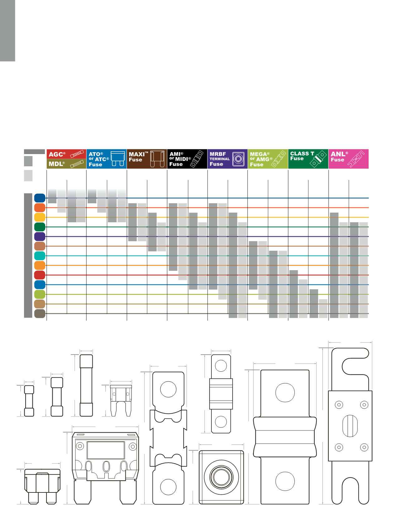
STEP 2 Choose the Correct Fuse and Fuse Amperage
L E G E N D
Outside
Engine
Room
Inside
Engine
Room
.25A to 30A
1A to 30A
30A to 80A
30A to 200A
30A to 300A
225A to 400A
35A to 400A
4|0
AWG
3|0
AWG
2|0
AWG
0
AWG
1
AWG
2
AWG
4
AWG
6
AWG
8
AWG
10
AWG
14
AWG
12
AWG
16
AWG
AWG W I R E S I Z E
100A to 300A
FUSE SELECTION CHART
25A
SINGLE
WIRE
BUNDLED
WIRES
SINGLE
WIRE
BUNDLED
WIRES
SINGLE
WIRE
BUNDLED
WIRES
SINGLE
WIRE
BUNDLED
WIRES
SINGLE
WIRE
BUNDLED
WIRES
SINGLE
WIRE
BUNDLED
WIRES
SINGLE
WIRE
BUNDLED
WIRES
SINGLE
WIRE
BUNDLED
WIRES
20A
20A
15A
25A
20A
20A
15A
30A
25A
20A
30A
25A
20A
30A
30A
30A
30A
30A
30A
30A
25A
30A
25A
50A
40A
30A
50A
40A
30A
50A
40A
30A
35A
60A
50A
40A
40A
60A
50A
40A
40A
60A
50A
40A
40A
50A
40A
40A
35A
80A
70A
60A
50A
80A
70A
60A
50A
80A
70A
60A
50A
80A
60A
50A
40A
80A
70A
125A
100A
80A
70A
125A
100A
80A
70A
125A
100A
130A
100A
70A
60A
150A
125A
125A
100A
150A
125A
125A
100A
150A
125A
125A
100A
150A
130A
100A
80A
200A
175A
150A
125A
200A
175A
150A
125A
200A
175A
150A
125A
200A
175A
150A
130A
200A
175A
150A
250A
200A
175A
150A
250A
200A
175A
150A
250A
250A
200A
175A
150A
200A
175A
300A
250A
200A
175A
300A
250A
200A
175A
300A
250A
300A
250A
200A
175A
300A
225A
200A
300A
225A
200A
350A
300A
225A
350A
300A
225A
200A
250A
225A
250A
225A
400A
350A
250A
225A
400A
350A
250A
225A
300A
250A
300A
250A
400A
400A
300A
250A
400A
400A
300A
250A
Calculations are based on 105°C wire.
For lower temperature rated wire, consult the Circuit Wizard at
www.circuitwizard.bluesea.comChoose a fuse from the list on the top of the
FUSE SELECTION CHART
by following along the line of the
AWG WIRE SIZE
determined from Step 1. Appropriate fuse amperage will have a gray bar that intersects the line.
The appropriate fuse amperage will be found in one of the four gray bars below the selected fuse type.
Single Wire, Outside Engine Room
= First column dark gray bar
Single Wire, Inside Engine Room
= First column light gray bar
Bundled Wire, Outside Engine Room
= Second column dark gray bar
Bundled Wire, Inside Engine Room
= Second column light gray bar
Calculations are based on 105°C wire.
For wire rated at 80°C or lower, use the fuse amperage for the next smaller wire size.
Example: For a 4 AWG single 105°C rated wire outside an engine room, the fuse amperage is 150A
Note: Possible fuse amperages for a circuit can fall between a range of maximum and minimum fuse amperages. The procedure above calculates the maximum fuse
amperage which reduces nuisance blows but may offer less protection than a lower amperage fuse. The minimum fuse amperage is calculated by multiplying the current
flow in amps by 125%. If the product instructions specify a fuse amperage, use that value if it is under the maximum amperage found in the above procedure.
If the specified fuse amperage is over the maximum suggested, move down the column and choose the wire size that intersects with the specified fuse amperage.
A
B
Full scale fuse
comparison:
ATO®/ATC®
MAXI
AMI®/MIDI®
MEGA®/AMG®
MRBF® Terminal
Class-T
ANL®
AGA®
GMA®
AGC®/MDL®
ATM®
Although this process uses information from ABYC E-11 to recommend wire size and circuit protection, it may not cover all of the unique characteristics that may
exist on a boat. If you have specific questions about your installation please consult an ABYC certified installer.


