
19
Specifications subject to change. See bluesea.com for current information.
B AT T E R Y M A N A G E M E N T
Related Products
HD-Series Battery Switches
Up to 600 Amps continuous rating for large diesel engines
Features
•
Tin-plated copper studs for maximum conductivity and corrosion resistance
•
Accepts up to 4/0 AWG (120 mm²) battery cables
•
Studs accept 1/2" (M12) ring terminals
•
7∕ 8" (22 mm) stud length accepts multiple cable terminals
•
Blue Sea Systems one-piece terminal stud design never loosens over time
•
One-piece stainless flange nuts ensure safe and secure connections
•
Fits most Perko and Guest low amperage battery switch hole patterns
•
Case design allows surface or rear mounting options
•
Tactile indicator conveys knob position by feel
•
Icon Circuit Identification Label Kit available 7902 - sold separately (p. 129)
Specifications
3000, 3001 3002, 3003, 11003
Cranking Rating: 10 sec.
2,750A
2,750A
Cranking Rating: 1 min.
1,325A
1,150A
Intermittent Rating: 5 min.
900A
700A
Continuous Rating
600A
500A
Voltage Max. Operating
32V DC
32V DC
Regulatory
E
marked, ISO 8846,UL Listed - UL 1107 electric power switches
Meets American Boat and Yacht Council (ABYC) requirements
Meets UL 1500 and SAE J1171 external ignition protection requirements
IP66—protected against powerful water jets (see inside back cover)
ON-OFF
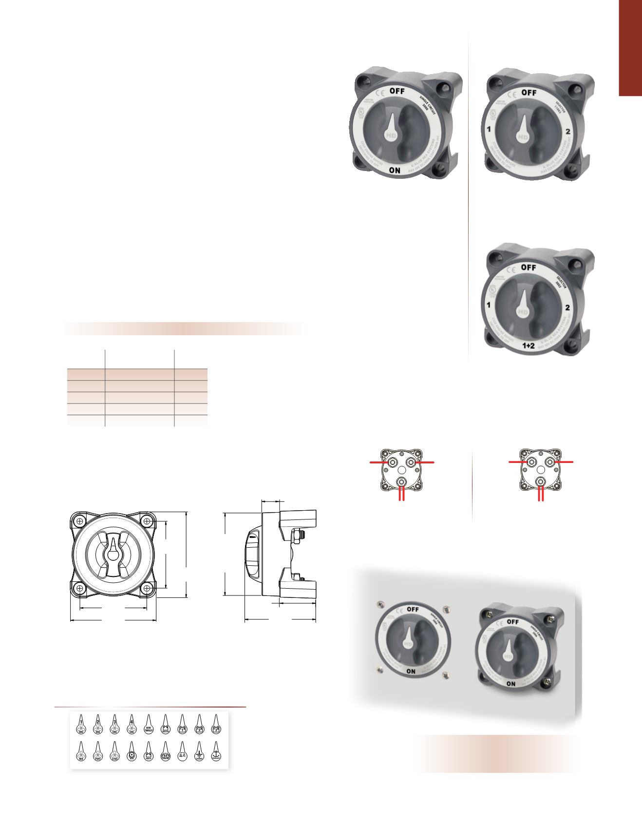
3000 and 3001 Connections
SELECTOR
3002, 3003, and 11003 Connections
3000, 3001 *
Single Circuit ON-OFF
Switches a single battery to
a single load group
3002, 3003 *
Selector 4 Position
Switches isolated battery banks
to all loads or combines battery
banks to all loads
11003 *
Selector 3 Position
Switches isolated battery banks
to all loads
COMMON
COMMON
BATTERY
COMMON
BATTERY 2
BATTERY 1
For the full list of specifications, see pages 20–21
* Includes Alternator Field Disconnect
(AFD) which protects the diodes in the
alternator in the event of the switch
being switched to the OFF position while
the engine is running. If the AFD is not
used to protect the alternator, an LED
can be connected to the AFD terminals
to indicate when the battery switch is in
any position but OFF.
Circuit Identification Label Kit
p. 129
3.00"
76.20mm
3.85"
97.79mm
3.00"
76.20mm
3.85"
97.79mm
REAR
PANEL
MOUNT IN
3-5
/
8"
92mm
Ø HOLE
1.59"
40.39mm
3.097"
78.67mm
0.77"
19.56mm
Rear
Front
INVERTER
CHASSIS
GENERATOR
PARALLEL
ENGINE1
BATTERY1 BATTERY2 BATTERY3
ENGINE
PORT
ENGINE
STARBOARD
ENGINE
MID
HOUSE
BOW
THRUSTER
WINDLASS
INVERTER GROUND
ENGINE4
ENGINE3
ENGINE2
For the complete list
of battery switch operational
diagrams, see pages 136–137
Mounting Options
PN
Description
AFD*
3000
Single Circuit ON-OFF
-
3001
Single Circuit ON-OFF
Yes
3002
Selector 4 Position
-
3003
Selector 4 Position
Yes
11003
Selector 3 Position
Yes
3000 and 3001 HD-Series ON-OFF battery switches have three studs; one stud for
the battery connections and two studs for the common load terminations.
3002 and 3003 HD-Series Selector battery switches also have three studs; but the
configuration is different with one stud for Battery 1, one stud for Battery 2, and
one stud for the common load terminations.


