
17
Specifications subject to change. See bluesea.com for current information.
B AT T E R Y M A N A G E M E N T
Related Products
Features
•
Tin-plated copper studs for maximum conductivity and corrosion resistance
•
Studs accept 3 ∕ 8" (M10) ring terminals
•
7∕ 8" (22 mm) stud length accepts multiple cable terminals
•
Blue Sea Systems one-piece terminal stud design never loosens over time
•
One-piece stainless flange nuts ensure safe and secure connections
•
Isolating cover with three snap-in side pieces protects rear contacts
and allows wire access in any direction
•
Case design allows surface, rear, or front panel mounting options
•
6 Circuit label set included (not included with 6005 and 6005200)
•
Circuit Identification Label Kit available 7902 - sold separately (p. 129)
•
Removable key - 6005, 6005200; removable knob - all others
Specifications
6005, 6006 6007 6010, 6011
6005200 6007200 6010200
6006200
6011200
Cranking Rating:
10 sec.
1,500A 1,500A 1,000A
per circuit
Cranking Rating:
1 min.
775A
775A 650A
per circuit
Intermittent Rating:
5 min.
500A
500A 450A
per circuit
Continuous Rating
300A
300A 300A
per circuit
Voltage Max. Operating
48V DC
32V DC 32V DC
Regulatory
E
marked, ISO 8846,UL Listed - UL 1107 electric power switches
Meets American Boat and Yacht Council (ABYC) requirements
Meets UL 1500 and SAE J1171 external ignition protection requirements
IP66—protected against powerful water jets
(see inside back cover)
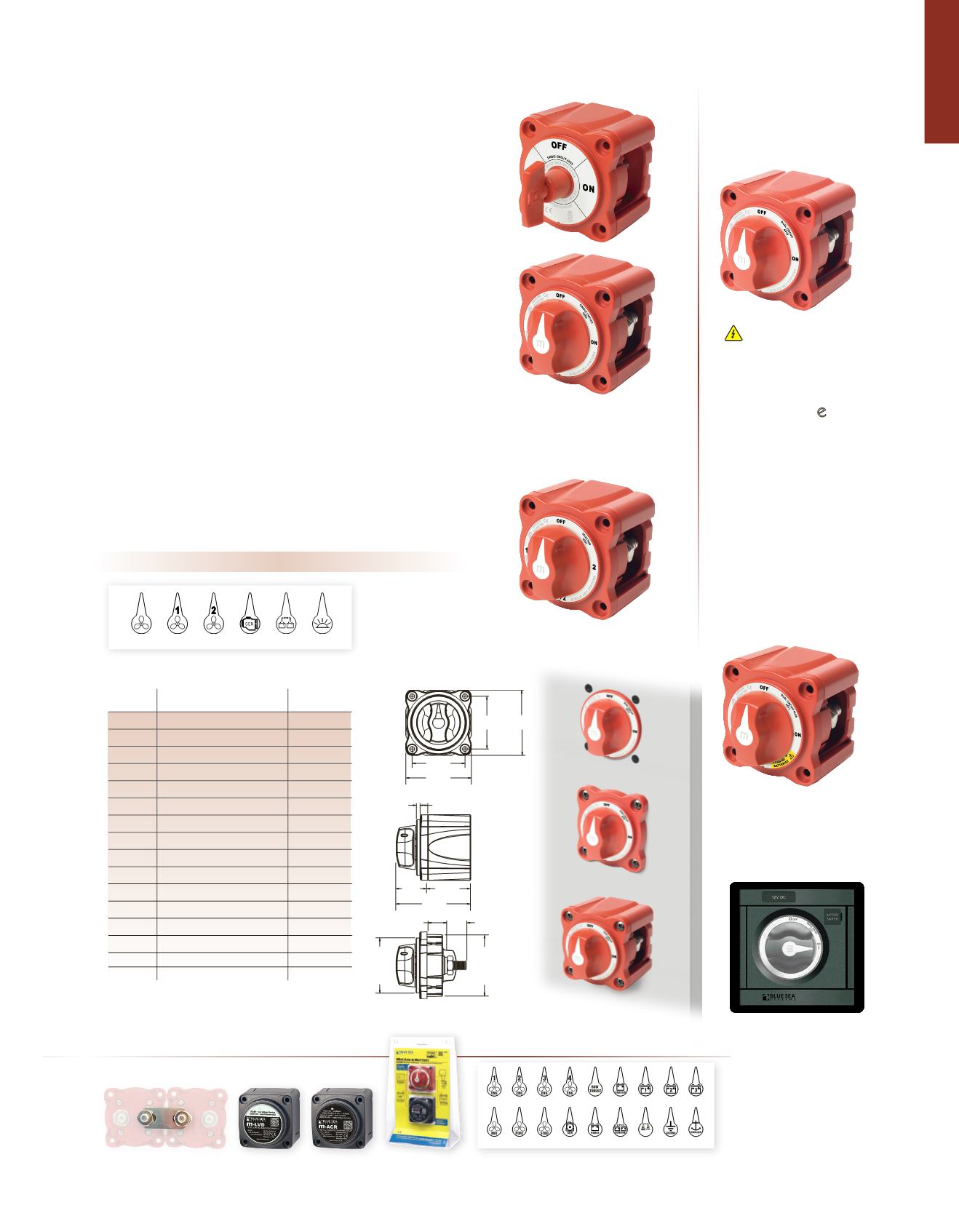
m
-Series Battery Switches
300 Amps continuous rating for outboards and small
gasoline or diesel engines
ENGINE ENGINE 1 ENGINE 2 GENERATOR PARALLEL
6 Circuit Label Set (included)
HOUSE
PN
Description
Color
6005
Single Circuit ON-OFF with Key
Red
6005200 Single Circuit ON-OFF with Key
Black
6006
Single Circuit ON-OFF
Red
6006200 Single Circuit ON-OFF
Black
6007
Selector 4 Position
Red
6007200 Selector 4 Position
Black
6010
Dual Circuit™
Red
6010200 Dual Circuit™
Black
6011
Dual Circuit Plus™
Red
6011200 Dual Circuit Plus™
Black
7900
Removable key
Red
7900200 Removable key
Black
7901
Removable knob
Red
7901200 Removable knob
Black
9159
Paralleling link bus (2 pack)
-
1139
360 Panel Battery Switch Module -
For the full list of specifications see pages 20–21
INVERTER
CHASSIS
GENERATOR
PARALLEL
ENGINE1
BATTERY1 BATTERY2 BATTERY3
ENGINE
PORT
ENGINE
STARBOARD
ENGINE
MID
HOUSE
BOW
THRUSTER
WINDLASS
INVERTER GROUND
Paralleling Link Bus
see table
Circuit Identification Label Kit
p. 129
m
-ACR
p. 30
Mini Add-A-Battery
p. 31
1139 (switch sold separately)
Dimensions (WxH):
4.88 x 4.75 in (123.83 x 120.65 mm)
•
360 Panel System
•
Accepts the m
-
Series Battery
Switch, m
-
ACR, or m-LVD
m
-LVD
p. 24
m
-Series
Battery Switch
Mounting Panel
2.825"
71.76mm
2.176"
55.27mm
2.825"
71.76mm
2.176"
55.27mm
0.153"
3.87mm
0.310"
7.87mm
1.298"
32.97mm
1.770"
44.96mm
3.068"
77.94mm
0.753"
19.11mm
0.900"
22.86mm
REAR
PANEL
MOUNT IN
2-5
/
16"
59mm
Ø HOLE
FRONT
PANEL
MOUNT IN
2-5
/
8"
67mm
Ø HOLE
6005
6010
6006
6007
Single Circuit ON-OFF
Switches a single battery to
a single load group
Selector 4 Position
Switches isolated battery banks
to all loads or combines battery
banks to all loads
Dual Circuit
™
Simultaneously switches
two isolated battery banks
or circuits. May be used
to switch the positive and
negative conductors for
required applications.
6011
Dual Circuit Plus
™
Simultaneously switches two
isolated battery banks or
combines battery banks to
all loads. CAN NOT be used
to switch positive and negative
conductors because of the
combine feature.
WARNING
The positive and negative conductors
should not be attached to the same
battery switch. The only exceptions
are the Dual Circuit Battery Switches,
PN 6010 and 5510
e
. Since these
models have electrically isolated
circuits and do not include a combine
feature, they can provide disconnect
to the positive and negative
conductors simultaneously.
Mounting Options
Rear
Surface
Front
ENGINE4
ENGINE3
ENGINE2


