
B AT T E R Y M A N A G E M E N T
16
Specifications subject to change. See bluesea.com for current information.
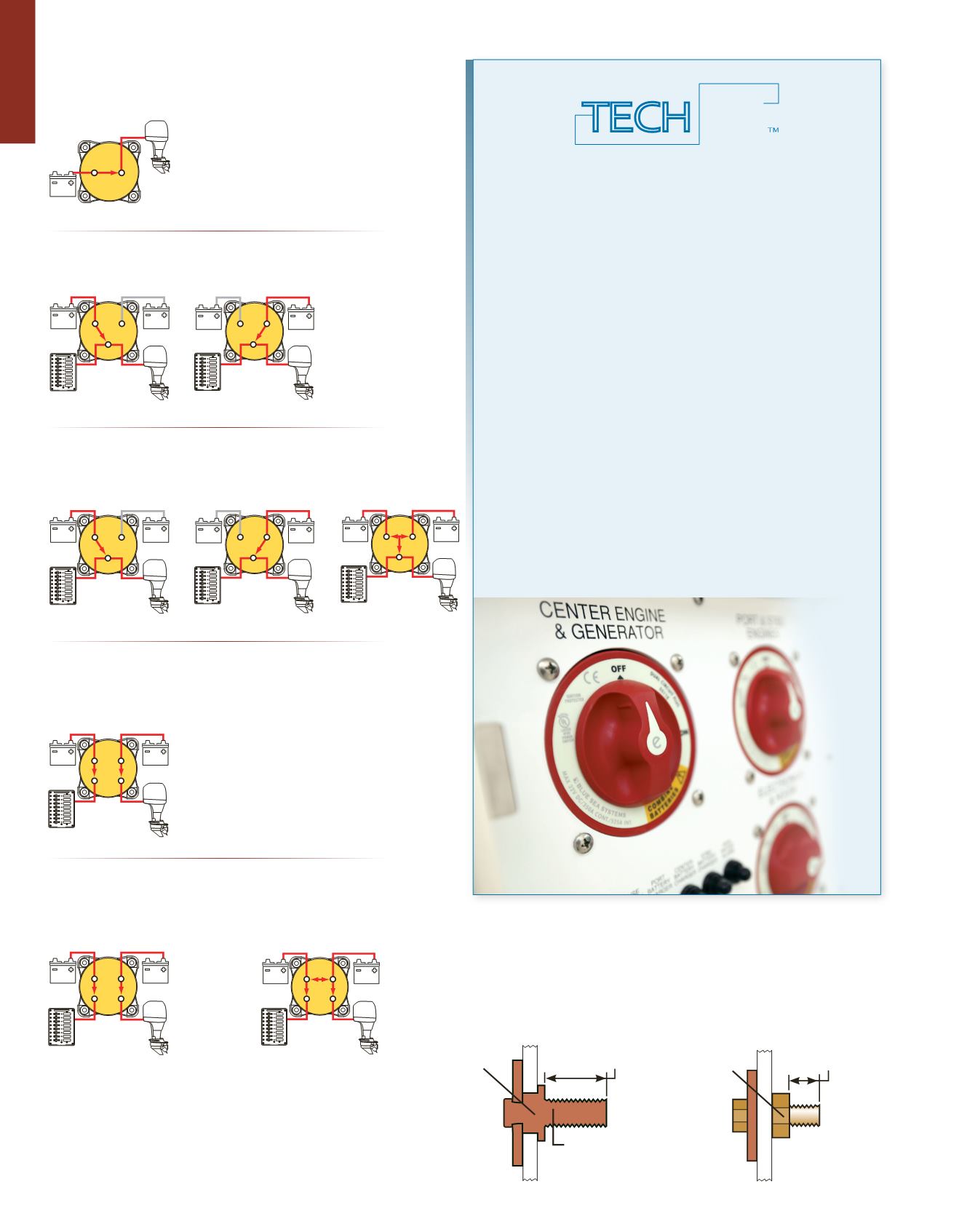
Battery Switch Operation Diagrams
UL Lising Information
Waterproof Rating IP66
Ignition protected
1 Piece Stud
Single Circuit ON-OFF
Switches a single battery to a single load group.
Selector 4 Position
Switches isolated battery banks to all loads or combines battery
banks to all loads.
Selector 3 Position
Switches isolated battery banks to all loads.
Dual Circuit™
Simultaneously switches two isolated battery banks or circuits.
May be used to switch the positive and negative conductors for
required applications.
Dual Circuit Plus™
Simultaneously switches two isolated battery banks or combines battery
banks to all loads. CAN NOT be used to switch positive and negative
conductors because of the combine feature.
Switch set to ON
Switch set to 1
Switch set to 2
Switch set to 1
Switch set to 2
Switch set to 1+2
Switch set to ON
Switch set to ON
Switch set to COMBINE BATTERIES
Blue Sea Systems
ONE PIECE STUD
Can never loosen over time
Competitors
TWO PIECE STUD
Can loosen and create a poor connection
Cold
formed
terminal
Tin-plated
electrical
copper
7/8"
(22 mm)
stud length
Vibration
may
loosen
nut
1/2"
(12.70 mm)
stud length
Blue Sea Systems One Piece Terminal Stud
Never Loosens Over Time
TECH
tip
by BLUE SEA SYSTEMS
The above operation diagrams are intended for reference of how the
switches operate and are not wiring diagrams. Consult an ABYC certified
marine electrical professional for system design and circuit protection.
Dual Circuit Plus
™
Explained
The Dual Circuit Plus™ was developed as a user friendly battery
switch to help prevent dead batteries. It is recommended when:
•
Ease of use is desired
•
Battery bank selection is not necessary
•
Using sensitive electronics
•
Paired with an Automatic Charging Relay (ACR)
The Dual Circuit Plus
™
is a double pole switch designed to supply
power to the devices that are connected to a specific battery bank.
This means house electronics are isolated from the engine bank. This
both preserves the starting battery and prevents sensitive electronics
from being subjected to voltage sags and spikes during starting.
Designed to be coupled with an Automatic Charging Relay (ACR) to
provide simultaneous charging of two battery banks from the engine’s
alternator. Below is a recommendation on how to properly use the
Dual Circuit Plus
™
Battery Switch when paired with an ACR.
1. Power is Needed - Turn the switch into the ON position.
2. No Power Needed (Storage) – Select OFF to prevent current
draw of both battery banks.
3. Emergency Parallel (Jump Starting) – Turn the switch to the
Combine Batteries position designated in yellow. Once the
engine is running, turn the switch to the ON position.


